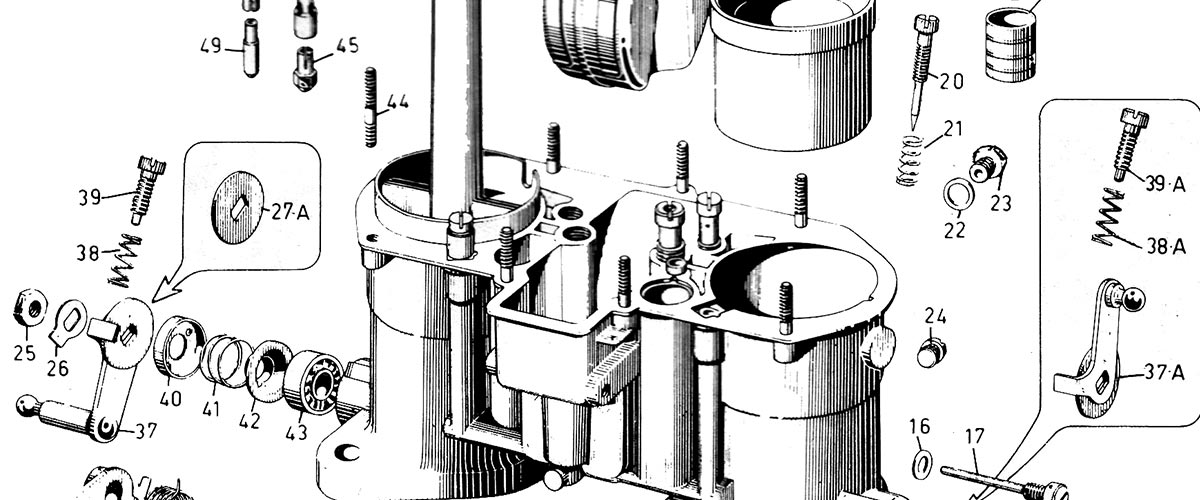
A look Inside the Weber carburetors
Scroll down for exploded views of the 48IDA downdraft, DCOE sidedraft, and the IDF downdraft carburetors. The main components for calibration and tuning are labelled below each image.
If you already own a Weber carburetion system and will be calling for tuning assistance, please remove the calibrated components as shown in these exploded views, and identify the sizes and numbers on the pieces when you call. That will help a great deal.
These exploded views are also shown inside the tuning manual that I include with every carburetion system.
Factory exploded view of a Weber 48IDA
Key components
#64: Jet Cover Screen.
LOW SPEED CIRCUIT
#49: Idle Jet
#50: Idle Jet Holder
MAIN CIRCUIT
#45: Main Jet
#46: Emulsion Tube
#47: Air Corrector Jet
#48: Main Jet Holder
ACCELERATOR PUMP CIRCUIT
#10: Pump Jet
#11: Accelerator Pump Exhaust Valve
FLOAT
#15: Float assembly
#17: Float fulcrum pin
#19: Choke


